
Rusted and frozen evaporator coil resulting in compromised performance.
An evaporator is a device in a process used to turn the liquid form of a chemical substance into its gaseous-form/vapour. The liquid is evaporated, or vaporized, into a gas form of the targeted substance in that process.
The vapour compression cycle is a brilliantly designed machine which, when designed and applied properly, can maintain a designated space at a temperature that is lower than that of the immediate surroundings. It accomplishes this by transferring heat from the space to a heat transfer medium—in the case of the vapour compression cycle, that medium is a refrigerant.
The ultimate goal of the vapour compression cycle is to transform the refrigerant into a saturated fluid at a temperature that is low enough to facilitate the heat transfer necessary to achieve the desired temperature in the space.
There are four required components in the vapour compression cycle, each having its own specific function which contributes to that ultimate goal:
Compressor: receives low pressure/low temperature vapour from the evaporator and transforms it into high pressure vapour. Heat is added to the vapour during the compression process, and it leaves the compressor as a high pressure/high temperature vapour.
Condenser: receives high pressure/high temperature vapour from the compressor and transfers heat from it. This allows it to change state from a vapour into a liquid. The liquid temperature is lower than the compressor discharge temperature, but still relatively warm.
Expansion Device: receives the high pressure/warm temperature liquid and forces it to undergo a pressure drop. Lowering the pressure allows the refrigerant to assume a new saturation temperature, which corresponds to the new lower pressure.
Evaporator: receives the low pressure/lower temperature saturated liquid from the expansion device, and it flows through the tubing in a finned-tube coil. The relatively warmer air in the space is circulated through the fins, allowing the heat from the air to be transferred to the saturated refrigerant in the tubing, thus cooling the space.
While each component in the system is of equal importance, the evaporator is where the space temperature reduction takes place, and it is simply the result of heat transfer.
Evaporator capacity is based upon several factors:
- Type of refrigerant
- Refrigerated space temperature
- Design condensing temperature
- Amount of heat to be removed (heat load)
- Humidity requirements for the space
For example, if the design requirement is to keep beverages at 35F in a refrigerated cabinet, then the system should be providing 25F saturated liquid refrigerant to the evaporator inlet. This will allow a 10F TD (temperature difference between air entering the evaporator fin-tube bundle and the saturated refrigerant flowing through the evaporator). This 10F difference allows the heat content in the higher temperature air to be transferred to the lower temperature refrigerant.
The amount of refrigerant necessary (mass flow rate) will depend on the type of refrigerant, the refrigeration load and the ambient condition. Of course, the design load is the maximum amount of heat transfer necessary to keep the product or space at the design temperature on the absolute most miserably hot and humid day in the summer time.
For the remainder of the year the equipment will be oversized. Yet, within a 24-hour period of any given day there will be continuous variations in the load (box doors being opened, product being loaded, changes in ambient temperature, etc.). To compensate for the varying load condition a thermostatic expansion valve (or electric expansion valve) will modulate open/closed regulating refrigerant mass flow in response to the load at any given moment.
Factors that affect evaporator performance can be broken down into two categories, air flow and refrigerant mass flow.
Air Flow
Evaporator capacity is, in part, based on the quantity of air flowing through the finned-tube bundle measured in cubic feet per minute (CFM). If any condition exists that would cause a reduction in the CFM, this will result in a reduction in evaporator capacity. For example:

Plugged filters will reduce air flow, which directly effects evaporator performance.
- Dust and dirt particles floating in the air are circulated through the exterior of the evaporator by the evaporator fans. These particles will accumulate on the evaporator fins and tubes. If evaporators are not cleaned periodically this buildup can seriously impede the air CFM, resulting in a loss of evaporator capacity.
- Air conditioning systems will employ filters to reduce the amount of dust/dirt that can foul the evaporator surface. Should these filters become restricted with a large buildup this will result in an air CFM reduction.
- Return air ducting, if undersized, will result in an air CFM reduction.
- If an evaporator fan has been replaced with a blade of the wrong pitch, this will result in an air CFM reduction.
- If an evaporator fan motor has been replaced with a motor with a lower RPM than the original motor, or a multi-speed motor incorrectly set up to operate at the wrong speed, this will result in an air CFM reduction.
- Evaporators utilizing belt drive motors are always susceptible to worn/slipping belts, which will result in an air CFM reduction.
- Evaporators with belt drive motors may utilize adjustable drive pulleys. If the pulleys are not adjusted correctly, this will result in an air CFM reduction.
Refrigerant Mass Flow
Evaporator capacity is also, in part, based on the refrigerant mass flow. At a given refrigerant saturation temperature there is a finite amount of heat that can be transferred to each lb. of refrigerant mass flow. As such, there will always be a specific requirement of refrigerant mass flow to meet the load demand at any given time. If any condition exists that would cause a reduction in the necessary refrigerant mass flow this too will result in a reduction in evaporator capacity.
- Many reduced refrigerant mass flow issues can be directly traced to an underfeeding thermostatic expansion valve (TXV). This can be the result of an incorrectly sized expansion valve, a faulty valve adjustment, contaminant buildup inside the valve causing a restriction in flow, a defective thermostatic element (which reduces the valve opening force), incorrect thermostatic charge, or in some cases bulb charge migration (where the element head is colder than the element bulb, and the charge migrates to the colder area).
- There is a certain percentage of liquid refrigerant that flashes into vapour during the expansion process and is directly proportional to the difference between the entering liquid temperature and the saturation temperature in the evaporator. If abnormally high condensing temperatures occur (resulting from a dirty condenser), this can reduce the liquid refrigerant mass flow entering the evaporator after the expansion process.
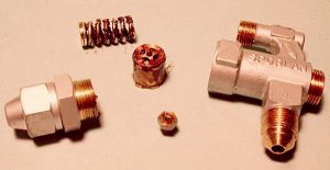
Contaminate buildup in a thermostatic expansion valve can restrict refrigerant flow.
- Expansion valves can only operate at their rated capacity if they are being fed by 100% liquid refrigerant. To achieve this, the liquid entering the expansion valve must be slightly subcooled. Otherwise, the refrigerant will start to change state into a vapour. If there is excessive liquid pressure drop (undersized liquid line, restrictions in the filter-drier, solenoid valve, etc.), the liquid pressure can drop to a point where some portion of the liquid will “flash” into a vapour. This will result in the expansion valve being fed with a mixture of liquid and vapour, reducing the available liquid mass flow entering the evaporator.
- Electric expansion valves are controlled by some type of electronic controller. There are certain parameters that must be entered for the controller to accurately control the valve. Among these are:
The total number of steps the valve travels from fully closed to fully open. For example, if the valve has a total of 2,500 steps, but the controller is set for 1,250 steps, the valve will never open more than 50% of its available stroke.
Each controller is programmed with several refrigerant options. For example, if the system is using R-404A, but the refrigerant parameter is set for R-22, the valve will not control accurately.
The superheat set-point must be entered for each application. If this is overlooked, or incorrectly set, it could result in the valve constantly underfeeding.
Understanding the function of the evaporator should assist the technician in garnering the maximum performance from it.
It should go without saying, in all systems great performance is directly proportional to precise set-up and commissioning. Maintaining that great performance is only possible with regular and thorough maintenance. <>
 Dave Demma holds a degree in refrigeration engineering and worked as a journeyman refrigeration technician before moving into the manufacturing sector where he regularly trains contractor and engineering groups. He can be reached at [email protected].
Advertisement
https://www.hpacmag.com/features/understanding-evaporators/

")


